
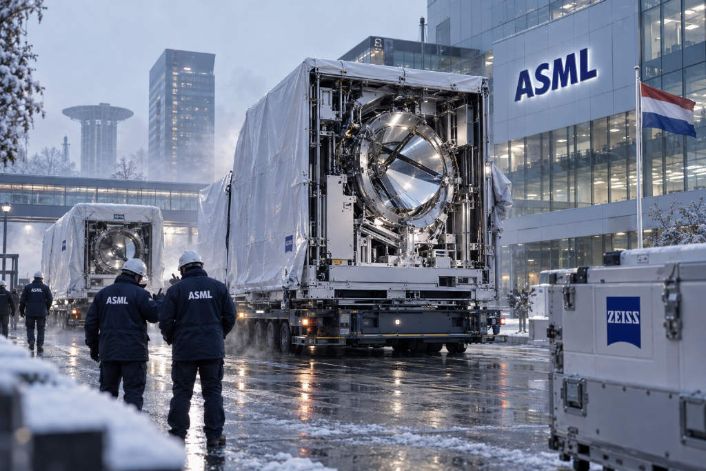
Hyper-NA is being positioned as the next extension of EUV lithography
Researchers from Carl Zeiss SMT and ASML have published a technical paper on EUV lithography with a numerical aperture of at least 0.75, describing the concept as a Hyper-NA scanner. In the paper, the approach is presented as the route beyond today’s 0.55-NA high-NA EUV systems. The discussion spans optical architecture, resolution potential, mask 3D effects, polarization, and what would be required to extend the current EUV ecosystem.

The paper says 0.55-NA EUV scanners have recently reached the market and are moving toward volume manufacturing. Because scanner development cycles are long, the follow-on product after 0.55 NA is already under consideration.
The authors propose raising numerical aperture to at least 0.75 while reusing as much of the existing lithography stack as possible, including masks, light sources, and the manufacturing equipment used to build scanners. Under the criteria set out in the paper — continuity with the current 13.5 nm EUV platform, reuse of source and mask infrastructure, compatibility with established scanner manufacturing technology, and limited change in system volume — Hyper-NA is described as the most direct extension of the current EUV scanner architecture.
A roadmap from 0.55 NA to 0.75 NA, aimed at 5 nm half-pitch resolution
The paper reviews the development of Zeiss lithography optics and says that, with only a few exceptions, those systems trace the same curve on a resolution-versus-time chart. The slope of that curve began to decline around 2010, which the authors interpret as a sign that turning higher optical resolution into smaller mass-production feature sizes is taking longer. Longer tool iteration cycles also reflect the larger effort needed to develop more complex optical systems.
By directly extrapolating that trend, the paper estimates that the next-generation tool should deliver 5 nm half-pitch optical resolution and come into use in roughly 10 years. The proposed way to reach that target is to increase numerical aperture to at least 0.75, which is why the paper labels the concept Hyper-NA.
The authors also compare different classes of projection-lens folding geometry and note that each class only works across a certain NA range. As NA rises from 0.25 to 0.75, lens size grows with it. The transition from low NA 0.33 to high NA 0.55 required new production equipment for larger lenses, especially new metrology to measure lens shape during manufacturing, though the effects were mostly confined to lens production itself.
What had much broader consequences in the move from 0.33 NA to 0.55 NA was the change in folding geometry, which drove a major increase in system size and affected fab floor-space requirements. By contrast, the move from 0.55 NA to 0.75 NA can stay within the same folding geometry. The paper says system size would barely increase, making the tool much easier to introduce into fabs and allowing integration with ASML’s future high-throughput scanner platform.
The paper adds that NA does not have to stop at 0.75. Optical designs up to NA 0.85 have already been developed. Still, the authors say higher NA drives a substantial increase in system size, which reduces the appeal of that option from both fab-space and manufacturing-cost perspectives.

Mask and source infrastructure are central to the proposal
Reuse of existing infrastructure is one of the main arguments made for Hyper-NA. For the light source, the paper says the case is straightforward. For masks, it compares the EUV angular distribution at the mask plane across different generations of tools.
Low-NA systems use anamorphic magnification differently from high-NA and Hyper-NA systems. In the paper’s description, low NA has an angular distribution close to circular, while high NA and Hyper-NA use non-isomorphic magnification with different horizontal and vertical magnifications, producing an angular distribution closer to an ellipse with an aspect ratio of about 1:2.
The challenge is to limit the maximum angle at the mask. If one simply scaled the 0.55-NA case, the sine of the maximum angle would rise by 36%. The paper argues that the high-NA concept already includes optical and mechanical improvements that substantially reduce that increase. Its baseline is to keep magnification at the high-NA values of 1/4 in x and 1/8 in y, while noting that a few percentage points of further adjustment could trim the maximum viewing angle a little more.
With those changes, the paper says a 0.75-NA Hyper-NA tool would see a maximum angle only about 1 degree higher than a high-NA system. The increase is described as mild, and the authors expect the current mask infrastructure could be reused with no changes or only very small ones. Initial detailed simulations of mask effects are cited as support for that view.
Two ways to use Hyper-NA: smaller features or more contrast
The paper says the extra numerical aperture can be used in two different ways. One is to print smaller structures while keeping NILS unchanged. The other is to use the higher NA to improve imaging contrast without shrinking the feature size, which the authors tie to better yield in high-volume manufacturing.
To show that, the paper compares image contrast under several levels of approximation. In the idealized case, contrast depends only on the diffraction orders interfering at the wafer, so each NA produces a finite series of step changes in the contrast curve. Once finite pupil fill is introduced, those abrupt transitions smooth out, but plateau regions tied to discrete NILS values remain. Adding resist blur tilts those plateaus slightly, at least for smaller half-pitches.
The blur parameter used in the paper is 2.0 nm at 1-sigma. The authors note that the analysis does not include resist thickness effects, thin-film absorption, standing-wave effects, or 3D mask and resist effects.
Vector effects and polarization are treated as application-specific trade-offs
The paper spends considerable time on vector effects, a topic that comes up frequently in discussions of Hyper-NA. When diffraction orders at the wafer are separated by larger angles, which happens for smaller features, only one of the two polarization directions can produce a fully contrasted aerial image.

If vector effects are ignored, and mask effects are also set aside for the sake of discussion, image contrast at fixed k1 would be independent of pitch. Once vector effects are included, which the paper treats as the real case, contrast changes with pitch even at constant k1. In some applications, polarization illumination can reduce that contrast loss.
The paper uses two extreme examples: line-space patterns and square contacts. For line-space imaging, the polarization required at the two poles of the illumination pupil is relatively clear, and the contrast loss caused by vector effects can be fully recovered.
Square contacts are more complicated. The paper says four different optimal polarization directions appear, one for each interfering pair of diffraction orders. Under the simplest mask model — an unbiased pure-amplitude Kirchhoff mask — the four polarization states contribute equally, so no preferred state exists and no polarization choice can outperform unpolarized illumination. With a more complex mask model, the contributions are no longer equal. In that case, polarization illumination offers a slight advantage, but the size of that advantage and even the best polarization state depend on the mask assumptions, including absorber type and bias.
For hexagonal contacts, each pole images feature directions that differ by 60 degrees, which allows a compromise polarization direction. The paper uses that to explain why polarization illumination only partially restores the image in that case.
The authors do not treat polarization as the default answer. Even where it improves contrast, they say the decision remains open because polarization illumination always comes with substantial light loss. The better choice is the one that reduces edge placement error, or EPE, the most.
EPE, shot noise, and the cost of polarization
The paper shows a current EPE budget for ASML EUV tools. One major contribution, shown in the rightmost block, is unrelated to optical properties and includes factors such as stage error, so it is outside the paper’s main scope. Another, smaller contribution depends on image contrast and can be improved with polarization illumination.
But the largest share of EPE depends on dose and contrast and is explicitly attributed to shot noise. That changes the trade-off. For any application, the paper says, one has to evaluate whether the EPE penalty caused by photon loss under polarized illumination outweighs the EPE gain from higher contrast.
If the implementation is based on an unpolarized source, introducing polarization means a substantial transmission penalty. The result is a direct comparison between contrast recovery from reduced vector effects and worse EPE caused by fewer photons. Even if a polarized source becomes available, the authors say the answer is still not obvious. Polarized sources may help for dense lines, but the case is less clear for the more important use of freeform polarization in complex structures.

A polarization path that builds on the existing illumination system
Even though many, and possibly most, applications would stay with unpolarized illumination to avoid losing valuable EUV power, the paper outlines a way to support polarization illumination in a Hyper-NA system for selected use cases. The proposed change is small: add linear polarizers to the current EUV illumination system to generate almost arbitrarily complex polarization distributions in the illumination pupil.
The paper briefly reviews the conventional illumination layout. Light from the EUV source enters the illuminator through an intermediate focus and illuminates the field-facet array. Each field facet then directs light to a corresponding pupil facet, and the light travels from the pupil facets to the mask.
The pupil facets form the illumination pupil. By tilting the field facets, different pupil facets can be illuminated, which changes the pupil setting. The use of hundreds of field facets and their matching pupil facets averages spatial fluctuations from the source and produces uniform, sharply defined illumination at the mask plane. The paper says the state of the art remains tin-based plasma sources producing several hundred watts of unpolarized EUV light.
Placing linear polarizers between the intermediate image point and the field facets would extend that system into a polarization-capable illuminator. The paper says this is a favorable location because any defects in the polarizers, such as mechanical supports that might cast shadows, would be averaged out by the rest of the illumination system. It also describes a linear polarizer made of two mirrors, each deflecting the beam by twice the Brewster angle.
With linear polarizers, the tool could generate not only global polarization but also freeform polarization in the illumination pupil. By placing a small number of linear polarizers side by side, different field facets would acquire different polarization states. Because field facets are tiltable, those states could then be distributed across the pupil in an arbitrary way, which is the basis of freeform polarization.
The paper adds that even if a polarized source such as a free-electron laser were used in the future, the two basic system configurations would remain the same. For applications dominated by parallel linear features, global linear polarization could fully remove the contrast loss caused by vector effects. For the more important case of irregular two-dimensional patterns, the paper points to the configuration with freeform polarization and a circularly polarized source, arguing that circular polarization can generate all required states with equal efficiency.
It also notes that polarization rotators or phase retarders could in principle replace linear polarizers and potentially avoid the light loss associated with them, but says there is currently no viable high-efficiency technology for polarization rotation or phase retardation at 13.5 nm or shorter wavelengths.

Manufacturing and inspection are presented as a continuation, not a reset
The paper argues that Hyper-NA can reuse existing manufacturing and inspection technology beyond the illumination system. It says image quality has improved sharply over more than a decade of EUV tool production, to the point where some metrics no longer need additional improvement.
The same logic is applied to Hyper-NA mirrors. According to the paper, the amount of aberration a system can tolerate does not depend on the exact NA value. A larger NA only means the same aberration requirements have to be met over a larger pupil area. That is why the manufacturing standard for Hyper-NA mirrors does not need to be stricter than it is for low-NA mirrors; what changes is the area over which surface quality must be maintained.
The paper also says recent low-NA development has shifted from lowering aberrations to supporting higher source power. Higher power raises throughput and, as the EPE discussion shows, can lower edge placement error. The authors say that matters for Hyper-NA because smaller structures require lower EPE. Existing low-NA technology can already handle higher source power, and larger Hyper-NA mirrors would spread the incoming power more evenly, which the paper says supports future source-power increases.
Depth of focus is the central challenge
The main engineering difficulty identified in the paper is the loss of usable depth of focus. Raising NA improves resolution, but depth of focus shrinks. Because depth of focus depends heavily on pattern and illumination conditions, the paper uses Rayleigh depth of focus only as a way to show how severe the challenge becomes when NA increases.
Under that framework, moving from NA 0.55 to NA 0.75 cuts depth of focus by about half. The paper says a reasonable first estimate is that both focus-control accuracy and resist thickness would need to improve by about the same factor.
Focus-control budgets in scanners have to cover several terms: residual scanner errors driven mainly by optical and mechanical defects, defects in wafer height topography, and pattern-dependent imaging effects that narrow the overlapping process window. The paper treats focus improvement as a joint engineering task for scanner makers and tool users, though it says there are already workable directions for improvement.
It also identifies resist improvement as essential, especially thinner resist films. Among the issues discussed are stochastic behavior and etch resistance, but the key point is whether a resist that is half as thick can still absorb enough photons. One option mentioned in the paper is increasing the metal mass fraction from about 1/4 today to 1/2, which could imply a shift toward dry resist or related changes.
A 0.75-NA micro exposure tool is proposed to support resist development
To make that resist work possible, the paper argues for a suitable micro exposure tool, or MET. It notes that early EUV lithography used a 0.3-NA MET and that BMET5, a 0.5-NA system, is still used for resist development today.

The paper describes the MET as a two-mirror projection system with holes in both mirrors, allowing light to pass through them. Using the same NA in the MET as in a scanner makes it possible to reproduce the wafer-side conditions and obtain realistic resist development. At the same time, the MET cannot fully reproduce the angular distribution at the mask because its incidence angle at the mask is smaller, so resist development would not be disturbed by possible mask defects.
Comparing MET layouts across NA values helps frame the Hyper-NA challenge. Starting from the original 0.3-NA MET, a rise to 0.75 NA increases the size of the upper mirror. A key measure of practicality is obscuration, or the fraction of incoming light lost because each mirror has a central opening. The relevant design parameter is the ratio between hole diameter and mirror diameter.
Under reasonable system parameters, the lower mirror becomes the main design bottleneck, according to the paper. One way to enlarge the lower mirror is to move the reticle farther from the rest of the optics. One way to shrink the opening is to move the mirror surfaces closer to the wafer.
The authors say they have developed a concept design for a 0.75-NA Hyper-NA MET. With a track length of 1 meter, it would provide a usable field of 150 × 15 μm. A 1/8 isomorphic magnification would let existing masks print structures with half-pitch down to 5 nm, allowing Hyper-NA resist development to begin before mask-writing tools capable of even finer structures become broadly available.
Using advances in optical manufacturing, the design is said to reach 30% linear obscuration, meaning 9% of the pupil area is blocked by the mirror openings. That compares with BMET5, which the paper lists at 50% linear obscuration and 25% area obscuration.
Why the paper argues for more NA before a shorter wavelength
The paper returns to the standard resolution expression, CD = k1·λ/NA, and says the historical path of lithography resolution has been shaped by alternating increases in numerical aperture and decreases in wavelength. Its summary of that history is simple: NA was pushed as far as practical before the industry moved to a shorter wavelength.
The reason, the paper says plainly, is economic. Raising NA allows existing infrastructure to be reused. Changing wavelength does not. That preference for more NA before a wavelength shift has remained consistent over the past several decades.
Hyper-NA is presented as the direct continuation of that logic at 13.5 nm EUV. The paper argues that there is still room to increase NA at 13.5 nm, and that doing so preserves the value of the current ecosystem. It repeats that the drop in depth of focus creates a need for new resist technology, but says the proposed MET provides a path to support that work.

The same continuity is claimed for masks, mask qualification, and source technology. Current EUV plasma sources could be reused directly. If higher source power is eventually needed to reduce the shot-noise term in EPE, the Hyper-NA system is described as ready for that step. Combined with the argument that mirror-manufacturing technology is already in place, the paper casts Hyper-NA as the most direct continuation of the current roadmap.
Beyond Hyper-NA, the paper expects wavelength reduction to become necessary
The paper also looks past Hyper-NA. It says that once NA is pushed into the 0.75 to 0.85 range expected for Hyper-NA, pushing still higher would run into physical limits. At that point, the next generation after Hyper-NA would likely require a shorter wavelength.
No wavelength choice has been settled, according to the paper. It points to several promising ranges where sufficient reflectivity may be possible, including about 6.7 nm and the water-window band. Work on multilayer mirrors, sources, resists, and masks for those regimes is underway, but the paper says it remains in the academic research stage rather than industrial deployment.
The paper’s conclusion
In its closing section, the paper defines Hyper-NA as EUV lithography with a numerical aperture of at least 0.75 and describes it as an evolutionary extension of the current EUV roadmap. Under the criteria laid out by the authors — scanner feasibility, source reuse, continuity of the mask ecosystem, continuity in optical manufacturing, limited increase in system volume, and near-term ecosystem readiness — 0.75 NA at 13.5 nm is presented as the next extension beyond today’s high-NA EUV generation.
The paper says a 0.75-NA scanner could keep system volume almost unchanged from the current high-NA generation, directly reuse existing EUV plasma sources, and fit into ASML’s future high-throughput platform to maximize commonality across EUV systems. Zeiss’ current EUV mirror quality is also described as already sufficient for Hyper-NA, without the need for tighter manufacturing standards.
From the supplier side, the authors argue, those factors lower the barrier to introduction. The main open challenge remains the reduction in usable depth of focus. Beyond thinner resists, the paper says scanner focus control, wafer flatness, and process control all need to improve. To support that work, it proposes a dedicated micro exposure tool for resist development.
The translated article was credited to the WeChat account Semiconductor Industry Watch (ID: icbank), with authorship listed as ASML & Zeiss.